Wednesday, December 17, 2014

Measuring Algol with the MMTO All-Sky Camera

I have an attraction to all-sky cameras ever since I developed one to detect aircraft moving in the vicinity of a laser guide star beacon we developed at the MMT twenty years ago.  At that time, I saw the value of an all sky camera beyond what at the time was seen to be mearly a way of checking for clouds without having to go outside.

The MMTO has continued to run its all sky camera for many many years, and they've even developed a simple user interface to grab the data, which is stored in FITS format -- perfect for doing science.

In the past, I've poked around with satellite and meteor detection with some good results, but nothing conclusive because I never came up with an overall plan.  There's still value in these projects -- I just need to come up with an actual project design.

Recently I've decided to go back to the MMTO all sky camera data -- once again without an actual plan --  and see if I could measure variable stars.  The one that instantly came to mind was Algol.  This is an eclipsing system in which star B passes in front of star A every 2.867 days, with the entire eclipse event taking about 10 hours.

So here's what I have to work with:

A typical MMTO All Sky Camera view

and here it is zoomed in on Algol:


Zoomed in on Algol and surrounding stars
So I've written some software to do simple aperture photometry on Algol and Gamma And and then show their relative photometry.

This data, as you can probably tell, is very noisy and pretty poor.  Maybe this small project will motivate me to get ahold of the MMTO and see if I can work with them on improving their system.

In any case, the photometric results are also noisy, but show some promise.  The following is a plot showing relative brightness on the vertical axis, and UT time (show in hours before and after 21 Nov 2014) on the horizontal axis.


Relative Photometry for three consecutive evenings


The photmetry is shown for three contiguous nights: 20, 21, and 22 November 2014 (red, green, blue, respectively).   A value of '1' on the vertical axis says that Algol and the comparison star (Gamma And) were the same brightness.  A value larger than 1 means that Algol is brighter, and a value less than one means that Algol is fainter.  It was predicted that Algol would be at minimum on the 20th and 22nd.  Looking at the plots, it seems as though I was able to catch those events. But the data is so noisy and otherwise crappy that I'm not too sure yet.  I base this on the photometry for 21 Nov, which should be a pretty flat line and isn't.  There is an auto-gain on this camera so maybe that's what's making the data appear so non-flat.

In any case, this is sorta fun and I'm going to work on this a bit more to see if I can improve the measurements and maybe see if I can make those "non-event" evenings look at a little more flat photometrically.

Saturday, December 13, 2014

Latest Podcasts And Camera Update

My latest Apogee Podcast is out over at 365DaysOfAstronomy.  I call this one "3D Mapping of Rings and Bubbles In Orion".
 
I also continue to do my daily "Jupiter Today" podcast, which you can watch here.  I've come up with a couple ideas for additional videos to begin going into more detail about the information I present in the podcast.  I still have no idea where this project is going, except that it's keeping the Jupiter system in the forefront of my mind.  The primary goal is to create a network of telescopes that will constantly monitor Jupiter.

It's been cloudy or otherwise overcast here for the past two weeks so I haven't been able to get out and work a little more with my new camera.  I'm looking forward to getting some research done with this thing, but of course the clouds need to cooperate.  I realized after I'd put the eyepiece barrel on the camera that I needed to take the lens out of the camera.  So with a little careful surgery, that's been done and before the clouds came I did confirm that I was able to get images through my scope.

Sunday, November 30, 2014

New Video Camera

Got the C525 the other day and yesterday I mounted the eyepiece barrel onto it.  I initially let the glue cure for 3 hours but that wasn't long enough, so it's been sitting overnight and tonight (11/30/14) will be the first night on the scope.  For testing purposes, I'll be a quick look at the moon with different settings.  I'll also point to a star field and see if anything can be picked up.  I also have the barlow lens which may for once find a purpose in my work.  This is the beginning of my evaluation of this camera to act as a science instrument.


Logitech C525 with 1.25" eyepiece barrel attached

Looking "Down The Barrel"


With the lens cap on


"First Light" hand-held with no other optics.  Jupiter above, ISS passing below

Saturday, November 22, 2014

Camera, Cards, and Jupiter Today

Camera

I just purchased a web camera that's going to be used in my research.  It's a Logitech C525

A Logitech C525 Web Cam


I'll be attaching a 1.25" eyepiece barrel to the front of this camera (wish me luck!) so I can slide it into the focuser of my (or any) telescope.

Sofar, I've identified three projects I can do with this camera:
  1. Jupiter observations
  2. Occultations of stars by asteroids / planets / moons
  3. Detecting lunar impacts
The camera is expected to arrive in a few days.  I'm looking forward to using this new tool to continue my research!

Cards

I've ordered new business cards so I can finally start spreading the word about the work I'm doing.  Here's a picture of the card:

My new business card


Jupiter Today

I've begun a daily podcast that I'm putting up on a YouTube channel.  Not sure exactly where this project is going, but now I'm committed and looking forward to doing this indefinitely.

Tuesday, October 21, 2014

Mars and Siding Spring

Ben Davidson put out this video last evening:


I immediately emailed him back with a response, explaining everything that he was seeing (and speculating about) except one series of images which I'm still baffled by (although I'm leaning toward an optical effect).

No response, and as of his latest video this morning, he's either ignored my email or not seen it.

Anyhow, here is my email to him in the hopes that he'll see this blog entry:

Ben -- I've been an observational and theoretical astronomer for 35
years.  All of the things you show on your video are things I've seen
before except one.  Let me go through it all in some detail:

00:34 - 00:37 Those donut shaped objects are NOT caused by the
atmosphere, but rather internal reflections in the optics of the
telescope.  The atmosphere causes stars and other non-resolved objects
in the sky to twinkle, but that wouldn't be detectable in these
images.  The donut shape is actually an image of the primary mirror of
the telescope with the secondary mirror blocking the center (the
"hole" in the donut).

00:50 - 01:34 All optical effects.  Optical coatings create some very
beautiful effects like this.  Seen 'em a million times.,,

01:35 - 02:00 more about this below

02:00 - 02:37 this is the one you're most confused about, but it's
obvious to those of us who have used cameras on telescopes what this
is.  In order for the camera to see the background stars, a fairly
long exposure needs to be taken (in this case I'd guess it's about one
second).  The camera, of course, is in "live" mode so it's just
shooting pictures continuously and displaying them -- but not at video
rates otherwise we wouldn't see those background stars.  The next two
frames that distort the image of Mars is the telescope slewing while
the exposure is being taken.  This causes the streaks and blobs that
you see.  While the telescope is slewing, there really isn't anything
interesting to see so they cut the feed.  I've attached some data
images ('boops') I've taken of the Jupiter system (for my photometry
work) where I've bumped the telescope while an exposure is being
taken.  As you can see -- the same "mysterious" extensions.  Jupiter
is overexposed but you can see the effect on the moons.

boops


Here is more proof.  Look at the attached image named 'mars3'.  These
are two images taken from your video tonight.  In both images, there
is a 'TOP' blob, and a 'BOTTOM' blob.  First notice that the distance
between the TOP blob and BOTTOM blob is the same in both images --
indicative of the same exposure time.  Also notice that the position
of the BOTTOM blob on the left image is in the same place the TOP blob
on the right image.  This means the telescope was slewing at a
continuous rate (as expected).


mars3


So no big deal -- I'd probably do the same thing and show people
something else other than the telescope slewing.  I hope my
explanation makes sense.

The one that sorta has me baffled is the image from 01:35 to 02:00.
The bright object in the middle of the field of view not only is
flickering like I haven't seen anything astronomical flicker, but it's
also moving against the background stars.  In the short time span that
this apparently covers, we would NOT see Mars move against the
background stars.  I can't account for the flickering at all, except
to say that maybe it's some kind of off optical effect (it usually
is).  Do you have any information on how this video was taken????

Hope this clears up most of it.

Great work.

Peace, CL

Wednesday, October 8, 2014

IRIS MgII measurements 2014-09-09

From 2014-09-09 05:48:07-07:44:33:

Figure 1: IRIS view of the sun at 2796A


Figure 2: The MgII k (left) and h (right) spectral lines

Tuesday, October 7, 2014

Third set of IRIS data

Some new measurements from data taken by IRIS on 12 September 2014

I've added an additional column to the data.  Column 11 is a measurement of the "power" in the given spectral line.  Here's a plot showing the MgII k and h power.  The x-axis is the power and the y-axis is the number of vertical arcseconds from the center of the Sun.


The total power corresponds as expected to the shape of the spectral lines: less power where the spectrum is dark, more power where the spectrum is bright ---


k (left) and h (right) MgII spectral lines

Although now apparent when looking at the image, the plot of total power shows that the h lines are typically brighter than the k lines.

Wednesday, October 1, 2014

More IRIS Data

I took some more recent data and ran it through my code to make these measurements and I'm very happy with the results.  I made a small modification to the peak finding code that made a huge difference in terms of positive detections.

Anyhow, the latest measurements are from data taken in 'Sit and Stare' mode on 2014-09-19 05:17:12-07:14:54.  This calibrated data is marked 'OBS 3860608353' and is available here.

My measurements are here, which is a zip file containing the data values.

Tuesday, September 30, 2014

IRIS Measurement Data At Last!

The first set of IRIS MgII h and k spectral feature data is available here.  The ZIP file is here.

The input calibrated data can be accessed here.

Measurements of MgII h and k lines

The singly ionized Magnesium h and k lines are a source of strong ultraviolet emission in the spectrum of the sun.  Each of these lines has features in their profiles that have been identified as k1r, k2r, k3, k2v, k1v, h1r, h2r, h3, h2v, and h1v.  The measurement of their wavelengths, intensities, and spacial locations is the purpose of this project.  The k1r, k1v, h1r, and h1v features are not included in this current project.

We start with a portion of the sun that is being observed in 'Sit-and-Stare' mode (see Figure 1) at a particular time.  Different data sets may have a different time interval between successive images/spectra.  In this figure, the thin black vertical line is the entrance slit for the spectrograph.  Notice that the slit intersects a sunspot about 2/3 of the way from the bottom of the image.

Figure 1


The spectrograph produces spectra at many different wavelength bands of interest, one of them being a band that covers the Mg II k and h lines, which are at approximately 2796.4A and 2803.5A respectively.  Figure 2 shows a typical h spacial-spectrum.  The x-axis corresponds to wavelength and the y-axis correponds to spacial location along the slit.


Figure 2


Figure 3 shows the identified spectral line features.  The red, green, and blue points identify the h2r, h3, and h2v features, respectively.  The x-axis is wavelength (in angstroms) and the y-axis is the number of vertical arcseconds away from the center of the sun.  Compare this to the input data (Figure 2) and you'll see that the algorithm is generally doing a fairly good job at feature identification.


Figure 3


Figure 4 shows a typical line profile for the h line, identifying the three features that will be measured.  Figure 5 is the same data, but zoomed in to show just the spectral features and their calculated pixel positions.


Figure 4


Figure 5


The algorithm scans the profile and calculates the difference in intensities between adjactent points.  When the difference flips between a positive difference and a negative difference, a peak has been found.  When the difference flips from negatice to positive, a trough has been found.  The exact location where the difference has a value of zero is the location of the peak or the trough.  Figure 6 shows the differences.  The black dots indicate where the differences are zero.  There is a 1/2 pixel offset between Figure 5 and Figure 6 values because the intensity differences are measured from the "centers" of the pixels while the intensities themselves are measured from the "edges" of the pixels.


Figure 6


Because of various factors, not all line features can be measured.  These features disappear, for example, in the location of the sunspot.  This algorithm is looking for a peak-trough-peak sequence and will fail proper identification if this sequence is not encountered (for instance if it finds a trough before the first peak, or if just a single peak is found).

Once the pixel location of the peak or trough has been calculated, it is translated into an spacial offset (in arcseconds away from the center of the sun) and wavelength (in angstroms), by using the "CRVAL1" and "CDELT1" metadata values provided in the FITS headers.  The intensity of the peak or trough is also measured and reported.

This is done separately for the k and h lines.

Currently, the software will only work with 'Sit-and-Stare' input data.

Data Example

The data is organized into separate text files corresponding to spectra taken at each raster epoch.  For example, if there are 144 raster images, then there will be 144 separate text files with the following type of data:

6912.522659 30 120.884 144.357 2803.386 1519.708 2803.537 1114.734 2803.614 1178.763 31539.500
6912.522659 31 120.884 144.523 2803.389 1504.800 2803.530 1235.172 2803.615 1337.240 31642.000
6912.522659 32 120.884 144.690 2803.406 1400.550 2803.518 1242.861 2803.607 1341.820 31097.500
6912.522659 33 120.884 144.856 2803.397 1384.531 2803.487 1195.102 2803.596 1341.308 30745.000
6912.522659 34 120.884 145.022 2803.394 1409.741 2803.474 1225.024 2803.580 1337.178 30260.750
6912.522659 35 120.884 145.189 2803.391 1395.913 2803.494 1173.014 2803.596 1392.362 29817.250
6912.522659 36 120.884 145.355 2803.389 1359.357 2803.485 1160.290 2803.597 1352.109 29595.250
6912.522659 37 120.884 145.521 2803.372 1312.136 2803.493 1140.555 2803.593 1333.213 29225.250
6912.522659 38 120.884 145.688 2803.358 1268.717 2803.488 1131.498 2803.601 1314.044 29207.000
6912.522659 39 120.884 145.854 2803.354 1316.627 2803.457 1084.482 2803.596 1335.140 29375.250
6912.522659 40 120.884 146.020 2803.350 1356.074 2803.476 991.637 2803.601 1320.630 28961.250
6912.522659 41 120.884 146.187 2803.342 1408.039 2803.470 968.719 2803.603 1325.508 29083.750
6912.522659 42 120.884 146.353 2803.343 1409.933 2803.469 967.708 2803.612 1352.689 29782.750
6912.522659 43 120.884 146.519 2803.344 1391.391 2803.465 1012.583 2803.611 1395.858 30408.750
6912.522659 44 120.884 146.686 2803.334 1380.299 2803.457 1033.055 2803.612 1392.879 30696.000
6912.522659 45 120.884 146.852 2803.355 1393.129 2803.467 1131.581 2803.593 1397.156 31680.500
6912.522659 46 120.884 147.018 2803.350 1509.836 2803.470 1211.112 2803.609 1413.840 32370.000
6912.522659 47 120.884 147.185 2803.350 1448.126 2803.471 1135.210 2803.612 1331.672 31034.500
6912.522659 48 120.884 147.351 2803.341 1351.033 2803.499 1047.807 2803.615 1278.129 29607.000
6912.522659 49 120.884 147.518 2803.350 1321.970 2803.485 1096.239 2803.618 1293.102 29079.750
6912.522659 50 120.884 147.684 2803.356 1274.051 2803.460 1117.601 2803.462 1130.555 28155.250
6912.522659 51 120.884 147.850 2803.358 1190.512 2803.453 1041.789 2803.478 1055.543 26629.000
6912.522659 52 120.884 148.017 2803.368 1084.548 2803.455 971.335 2803.467 978.182 24838.750
6912.522659 53 120.884 148.183 2803.399 1035.587 2803.500 984.569 2803.561 1060.511 24682.750
6912.522659 54 120.884 148.349 2803.383 1124.145 2803.387 1111.945 2803.420 1152.975 25633.500
6912.522659 55 120.884 148.516 2803.395 1224.889 2803.485 1129.833 2803.529 1163.413 26514.750
6912.522659 56 120.884 148.682 2803.393 1250.542 2803.437 1184.945 2803.467 1204.757 27016.500
6912.522659 57 120.884 148.848 2803.368 1227.481 2803.479 1162.977 2803.587 1244.195 26974.500
6912.522659 58 120.884 149.015 2803.378 1213.820 2803.453 1178.464 2803.480 1184.556 26797.500
The files will be named in the following format:

obs_AAAAAAAAAA_BBBBB[h/k].txt

where the A's correspond to the IRIS observation tag, and the B's correspond to the raster image number starting at '00000'.  'h' or 'k' corresponds, of course, to the spectral line.

Column Descriptions:

1:  Julian Date (JD - 2450000) of observation
2:  Raster image row number
3:  X position (arcsec) from center of Sun
4:  Y position (arcsec) from center of Sun
5:  Measured k/h2v position (angstroms)
6:  Measured k/h2v intensity (data units)
7:  Measured k/h3 position (angstroms)
8:  Measured k/h3 intensity (data units)
9:  Measured k/h2r position (angstroms)
10: Measured k/h2r intensity (data units)
11: Total power

IRIS is a NASA small explorer mission developed and operated by LMSAL with mission operations executed at NASA Ames Research center and major contributions to downlink communications funded by the Norwegian Space Center (NSC, Norway) through an ESA PRODEX contract.

Sunday, August 17, 2014

IRIS Data Products -- Almost

I was about to release my first set of IRIS data products and realized that I need to add a bit more data to the final product, AND most importantly I need to write up a document describing how I created the product.

I'm very excited about getting this data out, but it'll take a little more time to get it out.  The cool thing about being an independent researcher is that I can make my own timeline.  This way I can be satisfied with what I do rather than trying to finish on a schedule with only decent results.

Anyhow, here's a sample of the current data product:

20 -145.7258 2803.3411 7178.8491 2803.5112 4874.6631 2803.6743 6886.1235
21 -145.3931 2803.3596 6523.7871 2803.5061 4834.3359 2803.7090 6792.2446
22 -145.0604 2803.3843 7062.9453 2803.5510 5101.1875 2803.5935 5201.3462
23 -144.7277 2803.3965 7286.9478 2803.6162 4424.9214 2803.7390 5431.4185
24 -144.3950 2803.3757 7256.7803 2803.5818 4509.8062 2803.7209 5524.3799
25 -144.0623 2803.3625 7086.9365 2803.5273 3827.3635 2803.6963 5804.1982
26 -143.7296 2803.3557 7059.0205 2803.5303 3544.4858 2803.6841 5574.2578
27 -143.3969 2803.3569 6335.1782 2803.5208 3239.6372 2803.6741 4954.3608
28 -143.0642 2803.3591 5240.8706 2803.5232 2873.1086 2803.6799 4440.0874
29 -142.7315 2803.3716 4632.0991 2803.5444 2698.4321 2803.6804 3886.6016
30 -142.3988 2803.3906 4446.7124 2803.5581 2223.5918 2803.6794 3593.5039
31 -142.0661 2803.3838 4326.3809 2803.5452 1997.5411 2803.6750 3315.3245
32 -141.7334 2803.3789 4018.1577 2803.5532 2099.9224 2803.6716 3081.2000
33 -141.4007 2803.3850 3486.9858 2803.5474 2131.6660 2803.6533 2877.7717
34 -141.0680 2803.3813 2922.0916 2803.5286 1822.3867 2803.6533 2578.5029
35 -140.7353 2803.3828 2700.9463 2803.5337 1802.7117 2803.6450 2478.1128
36 -140.4026 2803.3909 2765.1562 2803.5225 1982.9794 2803.6292 2619.6548
37 -140.0699 2803.3962 2817.1248 2803.5288 2110.8174 2803.6179 2679.0667
38 -139.7372 2803.4019 2863.1106 2803.5273 2071.1104 2803.6245 2625.1670
39 -139.4045 2803.4031 3289.1108 2803.5190 2267.6670 2803.6216 2802.0623


The first column is the y-pixel location.  2nd column is the distance, in arc seconds, from the center of the sun along the y-axis of the image raster.  The next two columns is a pair: the first value (column 3) is the wavelength of the peak value of the MgII k 2v line, and the second value (column 4) is the intensity of that peak.  Columns 5 and 6, and 7 and 8 are the same, except they are for the MgII k 3 and MgII k 2r spectral features.

I need to add the distance from the center of the sun along the x-axis, and I need to add the UTC of the observation.  At the moment I'm only doing this for "sit-and-stare" data which means that the slit isn't scanning the image raster but is stationary.  I still need to work out how the scanning works as far as the data goes.  That'll come in a later version of the data product.

Here's a picture and a plot of the data that I'm working with:

Figure 1: The bright MgII h and k lines

Figure 2: A profile plot through the spectrum image above clearly showing the MgII h and k lines

IRIS is a NASA small explorer mission developed and operated by LMSAL with mission operations executed at NASA Ames Research center and major contributions to downlink communications funded by the Norwegian Space Center (NSC, Norway) through an ESA PRODEX contract.

Buttons

Nearly from day one that I owned my Roland Fantom X8, I've had trouble with the buttons.

I takes me a while to realize certain things, and this is an example.  Sit back for a short story:

When the first button went bad on my board, it was a button that was mounted on a small circuit board that was easy to replace -- and a mere $62.00.  Another two buttons on another circuit board failed.  I replaced that board for $160.00.  Yet another button failed on yet another circuit board and I replaced that for $140.00.  Then another button failed on the first circuit board -- the one that I had just replaced several months earlier.

So it finally dawned on me the other day that I might be able to just replace the buttons instead of the whole circuit boards.  I did a little online research and found that not only is this "button problem" a known problem, but most owners do just replace the buttons themselves.

So, with a soldering station set up, I went to work and replaced bad buttons with good ones.  A continuity test with a multi-meter confirms whether a button is working correctly or not.

Bang, bang, bang and I have a good-as-new circuit board with all the buttons working!

So now I hope to do this same thing with some other bad buttons I have on other circuit boards.  With all of the buttons replaced, I'll finally be able to get into actual sound synthesis.

Here's a picture of some of the bad buttons.  They're about 6mm wide.

Figure 1: Bad Buttons

Thursday, July 31, 2014

First Look At IRIS Data

I've started a project to measure line positions, intensities, and ratios of the MgII h and k spectral lines coming from IRIS.  I've got a little way to go before I can start publishing these values, but here's a plot showing my progress:

Figure 1: MgII h spectral line spacial and temporal data

Now as you can see, it's a moderately complex plot.  The x-axis is the number of arc seconds from the center of the sun along the vertical axis of the sun.  The y-axis is the wavelength, in angstroms, of the spectral feature.

The data points themselves show at least three distinct features, all sort of in the center of the plot.  The three lines around 2803.5 angstroms are showing the position of the peak(s) and trough(s) in the MgII h line.  So as you move from left to right on the plot, you're moving from south to north on the surface of the sun.  As you move from bottom to top on the plot, you're looking at longer wavelengths.

The top "line" (follow the dots going from left to right) is it's peak position and is represented by the designation "h2r".  The middle "line" is "h3", and the bottom "line" is "h2v".  The line at the bottom of the plot is an artifact from the program I wrote to detect the peaks and troughs of the spectral features.

The red "lines" were data taken at about 16:33 UTC on 27 June 2014 and the green "lines" were taken about 5 minutes later at 16:38 UTC.  You can see that over that fairly short amount of time, the spectral features have changed pretty significantly.

Notice how the typical double peak goes away at -115 to -100.  Why?  It's looking at a sunspot at that location.  Why do these spectral features vanish when looking at a sunspot?

That's all I can say about this for now.  Much more to do to make this data presentable and usable to the astronomical community.

Tuesday, July 29, 2014

The Evryscope Sky Survey System

In this Apogee podcast, Cosmic discusses purpose of sky survey telescopes, and details the work of one such system under development.

365 Days Of Astronomy Podcast

Sunday, July 20, 2014

Spinning Wheel

It's been a long while since I've recorded.  Not that I didn't want to or have any inspiration.  Nope.  A simple explaination: I have no way of recording.  My laptop died a few months ago and since then I've had to go without.  Luckily I was able to trade some of my time (my wealth is my time) for some computers that were being replaced.  Loaded audacity onto it and off I went with this first song.

I recorded most of it a couple weeks ago, but I knew at the time that there was something missing.  Today I listened again and realized that it needed a serious bottom.  Once that was complete, I had a song that could be put out.

Hope you enjoy.


Peace, CL

Wednesday, July 9, 2014

Fibonacci On Mars

I look at Mars images from HiRise and Curiosity pretty much every day.  I was scanning a HiRise image the other day, and saw this:


I loaded the image into gimp and enhanced it a little bit:


The original image is here.

Thursday, July 3, 2014

Distance to the moon, again

No data from last month, so I'm trying again.

Help me measure the distance to the Moon!

On the evening of 5 July 2014, the Moon will appear very close to the planet Mars.  At that time, I would like to get some help measuring the distance to the Moon.  What I need are pictures of the Moon and Mars taken at approximately the same time from as many different locations as possible.
  1. Set your camera up on a tripod for best image quality.
  2. Make sure that the picture you take has both all of the Moon and Mars in it, and that the focus is as good as you can make it.
  3. Email me the picture along with the time you took it (+/- 5 minutes) and your location (latitude and longitude, +/- 20 miles).
It'd be best if all images could be taken at appoximately the same time. Let's make this time 04:00 UTC (which would actually make it early morning 06 July in England), which is 21:00 PDT, 22:00 MDT, 23:00 CDT, and 00:00 EDT for the United States.

Tuesday, July 1, 2014

Free-Form Art

I started with this:


And after a few spontaeous modifications, I stopped when this appeared before me:


So that was kinda neat so I did this pair also:


Peace

Tuesday, June 10, 2014

Picture For Distance To The Moon

Here's my data:

pic taken approx 04:00 UTC 6/11/14
lat: 32N
long: 110W

Figure 1: My Moon/Saturn Pic Entry (Saturn is above and to the right of the Moon)
And I took a picture of the sky without the moon in the FOV just to see what the camera can do on a nearly full moon evening.  Not bad!


Figure 2: Not too bad for a cheap camera.  Moonglow seeping in at the top.  Very cool that the horizon is red!

Monday, June 2, 2014

Distance To The Moon

Help me measure the distance to the Moon!

On the evening of 10 June 2014, the Moon will appear approximately five degrees away from the planet Saturn.  At that time, I would like to get some help measuring the distance to the Moon.  What I need are pictures of the Moon and Saturn taken at approximately the same time from as many different locations as possible.

  • Set your camera up on a tripod for best image quality.
  • Make sure that the picture you take has both the Moon and Saturn in it, and that the focus is as good as you can make it.
  • Email me the picture along with the time you took it (+/- 5 minutes) and your location (latitude and longitude, +/- 20 miles).

It'd be best if all images could be taken at appoximately the same time.  Let's make this time 04:00 UTC (which would actually make it early morning 11 June in England), which is 21:00 PDT, 22:00 MDT, 23:00 CDT, and 00:00 EDT for the United States.

I did some test images with my little digital camera just set on 'Auto' and got some decent data looking at the Moon and Venus, and the Moon and Jupiter:

Figure 1: Moon and Venus

Figure 2: Moon and Jupiter
Email me your data (pictures) at cosmiclettuce AT yahoo DOT com.

Monday, May 26, 2014

Still Holding

Clouds and wind have conspired to bring this project to a screeching halt.

I'm seriously considering getting more into radio astronomy.

Sunday, May 11, 2014

Clear and Windy

Nothing much to update.  It's been mostly clear this past week, but also windy.  Wind bumps the scope around too much which makes for useless data.  I now have an even greater appreciation for domed observatories.

Saturn at opposition yesterday, 177 degrees away from the sun.

It's about time that I start to make the plots of the data I actually want to see: brightness versus orbital phase.  Stay tuned for that.

Saturday, May 3, 2014

Seeing Effects

Had a great session last night -- the first night in nearly two weeks!  My prediction that I'd get about half of the nights was very far off.  Sofar, since my Jupiter work started on 12 Feb 2014, I've had 14 observing sessions.  So that means that my "observing efficiency" is at 17.5% (14 / 80).

The surprise this evening was the seeing.  Towards the end of the session, I turned the scope to Saturn to start collecting 300 images of prelim data (I'm still assessing whether I can get "good enough" signal to noise to make the effort worthwhile) when just a little breeze blew through.  The breeze was enough to notice but it was brief and, I thought, uneventful.

However, this little breeze brought with it some nasty air!  The seeing went from really good to really bad in a matter of a couple minutes.  Check these images out of Saturn:

Figure 1: Saturn in good seeing and in bad seeing, minutes apart


Having high-resolution astronomical imaging in my background, I'm curious about these things and would like to understand them better.  I don't recall ever witnessing the seeing deteriorate so quickly.  I'd like to know what exactly causes this and how long it lasts.

I can't make a post to this blog without a nice picture of the Jupiter system from last night:


Figure 2: The Jupiter system 03:09 UTC 03 May 2014
Also some nice Jupiter moon events for May:

5/8     E eclipse R     04:06
        I eclipse R     05:52
5/11    I/E close       04:00
5/17    I/G/C close     04:00
5/18    I/E/C close     05:00
5/24    G eclipse R     03:31
        I eclipse R     04:10
05/26   C eclipse D     04:39

Saturday, April 26, 2014

Great Photometry

Looked at the data from 17 March 2014 UTC today and found it to be very clean.  Io and Ganymede were making a close approach to one another, so their light is combined in the plot below:

Figure 1: Photometry for 17 March 2014 UTC


In any case, this data looks really nice and I'm happy with the data collection and calibration process.  This data is now what I'd call "fully calibrated" in that the final "reduction" is now complete with respect to atmospheric extinction.  X-axis is the UTC time, and the y-axis is the brightness, in ADU (corrected such that this would be the brightness at the top of the atmosphere).

Wednesday, April 23, 2014

Surprise color, Saturn here I come

What does it mean when the atmospheric extinction is different for each moon of Jupiter?

Figure 1: Linear fit to compute Atmospheric Extinction


It means (as far as I can tell) that I'm seeing COLOR DIFFERENCES between the moons.  Very very cool.

In Figure 1, the x-axis is the sec(Z) value, and the y-axis is the photometric value (in ADUs).  The relationship between these two values is linear with a negative slope (objects get fainter as they get closer to the horizon).  But the fact that there are differences between the slopes for the different moons can only mean that I'm seeing color differences in those moons.

My system is looking through a 'green' filter:


Figure 2: The filter set I use

So what do the differences in color mean?  Well, I can say that moon A is "redder" or "bluer" than moon B.  But what does a larger or smaller slope mean in terms of color?

The atmosphere absorbs blue light more than red light.  So as the object gets lower and lower to the horizon, more blue is lost, which makes the object appear fainter.  What this tells me is that Ganymede is "bluer" than Europa and Io, and Io is slightly "bluer" than Europa.

The larger the negative slope, the "bluer" the object is.  This is a hard one to visualize, so I may have to correct this statement later.

I noticed all of this in some data I was looking at from 01 April 2014 and noticed these differences.  Since I have to go back and run all my data reduction software again on all the data, I figured I'd stop and take a look at this (and other things) to try to work out how I want to proceed with yet another surprise.

There have now been three surprises:
  1. Watching targets move in and out of Jupiter's shadow
  2. Watching targets occult or near-miss (I've seen the latter) each other and (I think) seeing a dimming event caused by targets' "atmosphere".
  3. Seeing the color differences between the targets
What else is in store for me?  I'm open for more suggestions, Mr. Jupiter.

I am GO for Saturn

I'm very excited to start my Saturn observations.  For starters, there are SEVEN moons to monitor, with orbital periods between 22.6 hours (Mimas) and 1903.7 hours (Iapetus).  They are all tidally locked, so I'll get the same sort of "full disk" view every orbit.  But in this case, the entire system is tilted at an angle of 26.73 degrees to the ecliptic (very similar to ours) which means I'm seeing more of one pole at a time.  Very photometrically dynamic, I would think.  We'll see.

Saturn opposition is 10 May 2014 - 16 days.  I found this interesting article about Saturn and most interesting is this:

Another interesting phenomenon to watch out for near opposition is known as the Seeliger effect. Also sometimes referred to as the “opposition surge,” this sudden brightening of the disk and rings is a subtle effect, as the globe of Saturn and all of those tiny little ice crystals reach 100% illumination. This effect can be noted to the naked eye on successive nights around opposition, and will get more prominent towards 2017. Coherent-backscattering of light has also been proposed as a possible explanation of this phenomenon. Perhaps a video sequence capturing this effect is in order for skilled astro-imagers in 2014.

According to the Wikipedia entry on 'Opposition Surge', the variation can be quite noticeable.

Just the distances involved are pretty awesome.  Jupiter is about 700 million km away.  Saturn is 1340 million km away -- nearly twice as far!

Approximate maximum elongations for the moons:

Mim: 28.6 arcsec (11 pixels)
Enc: 36.6 arcsec (14 pixels)
Tet: 45.4 arcsec (17 pixels)
Dio: 58.1 arcsec (22 pixels)
Rhe: 81.2 arcsec (31 pixels)
Tit: 188.2 arcsec (72 pixels)
Iap: 548.5 arcsec (210 pixels)

Some of those might be tough, but we'll see.  I should see the same "surprises" with the Saturn system as I do with Jupiter.

PLUS, there is the planet itself and those nice rings.  Since I'm not saturating, I should be able to track the lightcurve of these, also.

I think the signal-to-noise is going to be ok with a 0.2 second exposure.  I think any longer exposure will ruin my chances of getting photometry on Saturn itself.  So I'll suffer a bit with the S/N.

Here's a plot showing the signal from Iapetus -- one of the fainter ones for sure:


Figure 3: Signal from Iapetus


And here's another plor showing the signal from Titan:


Figure 4: Signal from Titan

Both of these plots, as you can see, are on the same scale.

I've calculated that the S/N for Iapetus and Titan are 14.7 and 41.5 respectively.  Anything over 10 is good enough for me, but it will be challenging and I'm anxious to see how noisy this data is.

All of this is very preliminary as I collect more data.  I only took 100 images the other evening, and many of those will be garbage.  So at this point I'd guess that I've got maybe 50 data points on this stuff.  More data required to see how it's going to all work out.  As usual, I'll let the data guide me.

Monday, April 21, 2014

More great data and a surprise

I had two nice sessions in the past week -- last 15 April 2014 and yesterday evening 21 April 2014.  Here's a pic from last night:

Figure 1: The Jupiter system 03:25 UTC 21 April 2014
I have a LOT to talk about, but I've been otherwise occupied so a detailed update will continue to have to wait.

The surprise is that I'm very close to deciding that the Saturn system will be my next target.  My expectations were that I might be able to see Titan, but what I actually was able to see blew me away.  Take a look:


Figure 2: Saturn 05:39 UTC 21 April 2014
Iapetus!

Figure 3: The Saturn system 05:39 UTC 21 April 2014
Titan, Rhea, Tethys, and Dione:

Figure 4: The Saturn system
So -- should I start working with the Saturn system?  I probably will.  I need to look carefully at the signal to noise and also see if I can increase the camera exposure time by a little bit to help.

But, at this point it looks like I'll probably start looking at Saturn.  It's in a perfect place in the sky that I'll be able to watch it for the next several months.

More details on Jupiter a little later -- promise.

Saturday, April 12, 2014

Unusual Light On Mars

The Curiosity rover on Mars imaged some unusual events the other day.  Here's the link to the NASA press release.

It's most likely that these "raw" images have been calibrated in some way. Normal CCD calibration includes removing cosmic ray events. I would expect that a paper has been published on the calibration procedure for Curiosity (MSL). I'm going to try to find it. Because -- if cosmic ray events are removed, then it's hard to imagine that this is a cosmic ray event.

I've spent quite a bit of time over the years looking at Mars images. I don't recall ever seeing a cosmic ray event on any Mars images, although they clearly should happen very very often (my own experience with astronomical imaging tells me this). Perhaps since these cameras are "hardened" for space, they block most cosmic ray events? I find that theory doubtful.  The NASA people say that cosmic ray events appear on images "nearly every week" but as I said I don't ever remember seeing one.

So I have a hard time with the cosmic ray explanation.

I also can't be too sure about the "glint" theory. Only one of the navcams saw this (the right one). The left navcam image, taken at the same time, shows nothing unusual. Check it out yourself at http://mars.jpl.nasa.gov/msl/multimedia/raw/ Left/Right Navigation Camera, Sol 559, timetag 2014-04-03 10:00:03 UTC. The earlier one is Sol 558, timetag 2014-04-02 09:04:28 UTC. Same thing: right navcam shows the event, left doesn't.

I have no theory as to what this is. I make two additional observations:

Obs 1: These events are 24h 55m 35s apart. A "solar day" on Mars is 24h 39m 35s. A close correlation.

Obs 2: Looking at the two images and blinking between them, it seems to me that whatever it is, it's in the same location on the surface in both images.

However, I can't come up with an explanation as to why a glint would appear in one camera and not in the other. Cosmic rays could, however. But as I said above, I would think that cosmic rays would be filtered out during calibration. Then to have two in as many days doesn't seem likely.

I think they should turn around and take a closer look. They have 30+ years of power, so why not? That rover should live up to it's name and here's a perfect chance to do so.

Tuesday, April 8, 2014

More Data, Calibration Woes, Io and Europa, Relative Photometry

More Data

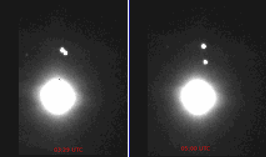
Another good session last night.  It was still pretty cold so I just ran for a couple hours -- from 02:49 to 05:21.  I was aware that an Io egress was supposed to happen, but I couldn't remember when it was and because of my setup, it wasn't easy to check.  So I didn't pay much attention and just enjoyed "sitting back" and watching the show.

Indeed at about 03:43 (I have no way of confirming this since I didn't actually record it, but this site says so) Io appeared.  Here's a before and after image set:

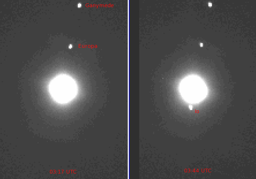
Figure 1: The Jupiter system showing Io egress


I did a hand-eye measurement of the distance between Io and Jupiter and got 42.12 arcseconds.  According to this site, the distance was 39.24 arcseconds.  So I'm within one pixel of the predicted distance.  Not bad.

Calibration Woes

I'm seeing two problems with the data and I think they're both systematic and I hope measureable and calibratable.  The first one I've alluded to in previous posts -- the tendency for the targets to be "bright" when they enter the field of view and slowly "dim" as they move across the FOV.  This is a general tendency but not 100% consistent.

I took some data last night that should show this problem if it's something inherent with the hardware.  A series of fifteen, 1 minute exposures were taken to produce star streaks across the entire array.  The results all look about like this:


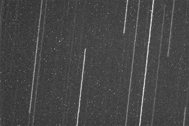
Figure 2: 1 minute exposure star trails
A plot along the bright trail on the right in this image produces this:


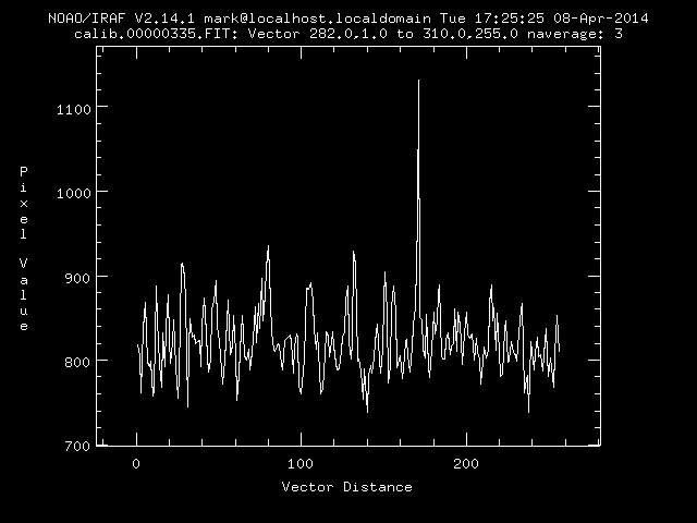
Figure 3: Plot along a bright trail

As you can see, except for some wiggles, there is no general tendency for the target to be brighter when entering the image (the left side of the plot) and progressively fainter as it leaves the image (the right side of the plot).

So what accounts for what I'm seeing in the data?  I don't know (yet!).

The other systematic problem I'm seeing is that the data seems to get noisier as the night progresses.  The following is a plot of the brightness of Callisto as a function of time.  As you can see, the data at the beginning of the night is pretty tight.  At the end of the night, however, the data is quite a bit more scattered (although the mean looks consistent).


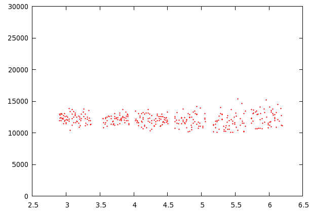
Figure 4: Callisto photometry 02 April 2014 UTC


Why?  This data has been corrected for atmospheric extinction, so why am I seeing this progressively larger scatter?

I've seen this in other data.  My only guess at this moment is that there are other factors with extinction that I'm not taking into account.  I don't think it's higher-order terms since the overall plot looks "flat".  However, something is making this data scatter more, and the only thing that's changing on my end is that I'm looking through progressively more atmosphere.

Io and Europa Mutual Event

During the 02 April 2014 UTC sesssion, Io and Europa passed very close to one another.  Here's a picture of the event:


Figure 5: Io and Europa in a near miss


My software would see the image on the left as a single target and will therefore show a brightness that's the combination of the two moons.  Over time, the two separate enough to allow the software to detect both as separate targets.  The photometry for each will settle into its spot.  This is indeed what I've got, with some surprises.


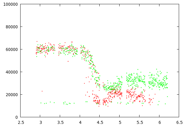
Figure 6: Io and Europa photometry during a mutual event


The green points are Io, and the red points are Europa.  Europa was speeding towards the back of Jupiter at the time, and at about 05:51 UTC it got too far into the bright disk of Jupiter to be detected by my software.

So indeed at the beginning of the session, the two moons has a combined brightness.  At about 04:07 UTC, they started to separate enough that they began to appear like two targets instead of one.  This took place over the course of several minutes (about 04:07 to 04:28 UTC) until as you can see on the right side of the plot, there are two distinct targets with different brightnesses.

However, there are structures within these plots that I can't account for.  Looking at the Io data (the green points), there's a very obvious smooth drop in brightness from about 04:30 to 05:00 UTC.  After that, the photometry looks pretty steady (with the exception of the aforementioned larger scatter).

This same dip in brightness appears in the Europa data but for a shorter period of time (about 04:30 to 04:43 UTC).  Europa is close enough to Jupiter that I'm not sure how seriously to take the points after about 05:00 UTC.

I should probably write a simulation to see perhaps more clearly what the photometry is supposed to be doing.  But my guess is that those dips probably shouldn't be there unless there's something else going on.

My only guess at the moment is that maybe I'm seeing the "atmospheres" of these two moons as suggested by Degenhardt in what he calls "atmospheric extinction".

Relative Photometry

Because of the ongoing systematic problems, I'm inclined to take a hard look at doing relative photometry and see if these problems sort of "go away".  The problem with relative photometry is that I'm not going to be able to easily separate out which moon is contributing what to the resulting light curves.  Once in a while I'll get a bright-enough star in the FOV, but I can't rely on that so the curves will be one target's brightness compared to another's.

Asteroid Data Hunter

This project is a joke.  I don't say this because I lost the first phase, but because the entries are nothing like what's needed to detect asteroids.  So I've decided to not waste my energy on this and instead work on something more direct -- especially since I now have actual data to work with.  Here's part of an email that I've sent to the PI for the CSS:

Part of my reason for writing you is to tell you that this winning Problem Statement is seriously flawed.  It's not flawed because the creator is stupid or a poor writer, or that the reviewer is stupid.  It's flawed because of ignorance about the problem itself.  The winning Problem Statement document very clearly shows this ignorance, and the fact that it won the competition shows this ignorance extends to the reviewer.  For example, things that are irrelevant to asteroid detection and astronomical imaging in general are included, and things that are very relevant are left out.  The blind are leading the blind.
...
I've come to the conclusion that this competition will fail to produce the results you're looking for.  The law of "garbage in, garbage out" applies. You cannot simply *hope* that a reasonable algorithm results from this competition.  With what I've seen so far, it would be *incredible luck* that you get anything that works at all -- much less, better than what you already have.

I've further come to the conclusion that my entry will fall onto the ignorant eyes of the reviewers and testers.  Because of MY ignorance about the details of how TopCoder works -- and despite my best efforts -- my entry will most likely fail.  I'll be producing oranges instead of apples again.  My work will be ignored not because it's a terrible solution, but because it doesn't fit within the flawed parameters set forth.  I'd prefer that to not happen.
...
I want you to be as successful in detecting as many asteroids (NEOs or otherwise) as you possibly.can.  I want the algorithm I've developed to be used for this important and exciting work.  So I give you an unsolicited gift: Everything I have in regards to asteroid detection is yours.  No strings attached.  No acknowledgement or compensation necessary.  I will work with you at any level you wish to make this happen.
...
I'm sure you'll see the value in what I'm giving you and I hope you won't blow me off as some idiot guy who *thinks* he has the best solution to a very difficult problem and is just angry about not winning the competition.  I don't care about winning or losing.  I also don't claim to have the best solution.  I claim to have a solution that produces very accurate and reliable results.  I'm certain you'll be pleased to see that for yourself.

I have two sets of the their data -- two sets of four images.  I also have their detection and rejection files.  So my plan is to proceed and get some code written to do what I described in my ADH phase 1 entry paper.